Single Antenna INS Mounting Instructions
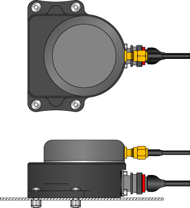
The general dimensions of the Single Antenna Tactical unit are shown above. See below for mounting options and how the unit's layout changes with each installation option.
There are 3 mounting options available for the single antenna INS: temporary external, permanent external, or permanent internal mounting. The choice between external and internal mounting must be made when ordering, since different hardware is required for each case. The mounting instructions for all 3 options are presented below.
1. Temporary external mounting.
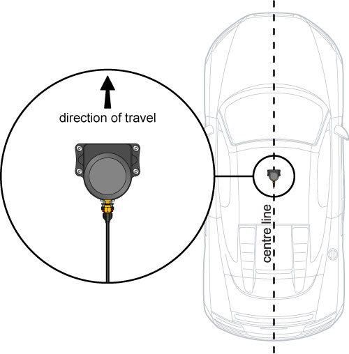
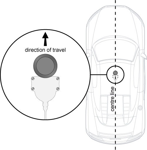
This mounting option is ideal for testing of multiple different vehicles where rapid fitment and removal is required, or in situations where it is not possible to drill any holes for permanent fixing. For the temporary mounting, the antenna assembly is mounted to the roof magnetically. The unit is supplied pre-bolted to a stainless steel plate containing 3 magnetic mounting points. The magnets are covered in a thin membrane to prevent damage to paintwork. This membrane should be periodically inspected before fitment, and renewed if required. The complete antenna and magnetic mounting assembly is shown in figure 1. The direction of travel is also shown. It is crucial that the correct direction of travel is adhered to; the cable attachments must be at the rear of the assembly. The rear-most mounting point is fitted with a securing strap for the IMU cable; this should always be used as shown in figure 1 otherwise flexing movement of the cable can damage the connector internally. Note that the GPS cable (the thinner one) runs above the securing strap - please refer to figure 1 for clarification.
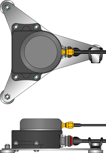
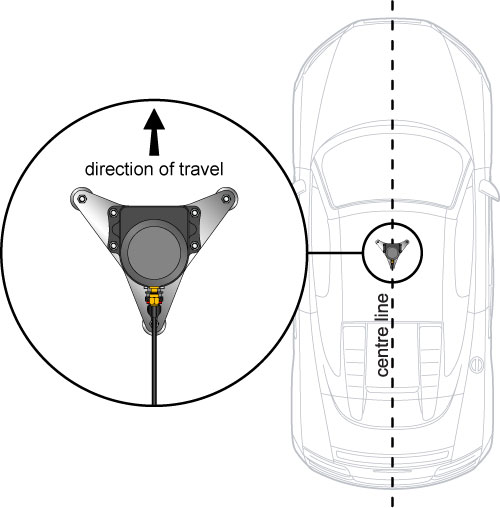
Figure 1
The magnetic mounting assembly has been tested on road vehicles up to normal fast road speeds (~130kph) and on the track up to moderate race speeds (~170kph), and has proved absolutely secure at those speeds. At higher race speeds or with extreme vibration the security of the mounting should be initially assessed with a security tether fitted, and it may be that the permanent mounting option may be required.
2. Permanent external mounting
This mounting option is ideal when a permanent mounting with minimal complexity is required. In addition, the antenna assembly can be easily unbolted from the permanent mounting and bolted to the magnetic mounting plate for temporary installation on other vehicles. This mounting option is essentially the same as the temporary external option, except that the 4 holes are drilled in the vehicle roof and the antenna assembly is bolted to the vehicle. The assembly and direction of travel are shown in figure 2 below. It is crucial that the correct direction of travel is adhered to; the cable attachments must be at the rear of the assembly. Note also that it will be necessary to secure the main IMU cable sufficiently to avoid flexing movement damaging the connector internally - simply using a cable tie to secure to a fixed location within 30cm of the connector would be sufficient.
Figure 2
The dimensions for the holes required are shown in figure 3 below:
Figure 3
3. Permanent internal mounting
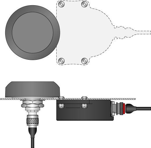
This is the ideal option for a permanent install where the minimum obstruction to airflow is required. The downside is that it involves the most drilling into the vehicle. This mounting option must be specified when purchasing the unit, since the hardware supplied is different, and the SPEEDBOX-INS must be factory configured to expect this mounting orientation. In this mounting option, the GPS antenna is the only component mounted on the outside of the vehicle, and the IMU assembly is mounted upside-down on the inside of the vehicle roof. The distance between the GPS antenna and the IMU assembly must be kept as close to the template shown as possible both horizontally and vertically, since this “lever arm” distance is compensated for in the firmware when this mounting is specified, and any deviation will result in an uncompensated lever-arm affect, which is undesirable.
The hardware and direction of travel for this mounting option are shown in figure 4 below, and the mounting hole dimensions are shown in figure 5. Note also that it will be necessary to secure the main IMU cable sufficiently to avoid flexing movement damaging the connector internally - simply using a cable tie to secure to a fixed location within 30cm of the connector would be sufficient, the closer the tie down is to the connector the better.
Figure 4
Figure 5