Output Drivers
With the output driver option enabled on the DASH2 PRO, up to four of the analogue input channels can be used as output drivers, each output driver is capable of sinking up to 500mA. When the output is active the output pin is driven to ground, so the load must be connected between a supply and the pin, NOT between the output pin and ground. The output drivers are updated at 10Hz.
The four output drivers are connected to inputs pins as follows:
| Output driver
| Pin
|
| 01
| 1
|
| 02
| 2
|
| 03
| 13
|
| 04
| 12
|
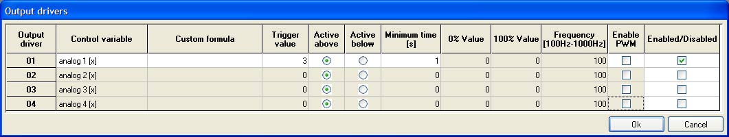
The output pins are configured from the Output Drivers icon on the DASH2 PRO configuration software.
There are two output modes for the output drivers, On/Off control, and PWM output.
On/Off control
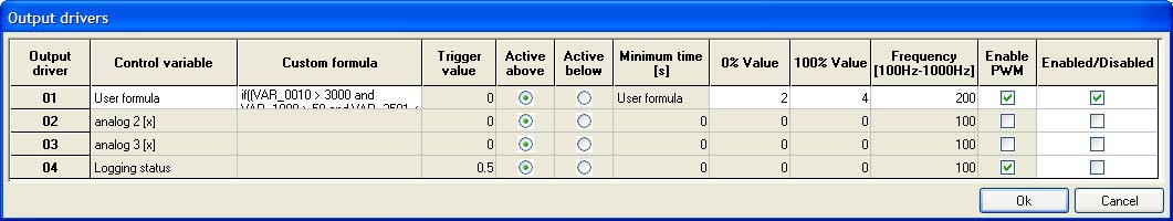
For the On/Off control mode, a control variable must be selected, this can either be one of the built in channels, or if ‘user variable’ is selected from the control variable list an equation can be used in the custom formula box. The custom formula enables very powerful control of the outputs. For example, by using the custom equation: if((VAR_0010 > 3000 and VAR_1008 > 50 and VAR_3501 < 2),1,0), will mean that if:
Engine speed > 3000rpm, and
Water temperature >50 degrees C, and
Oil pressure < 2 bar
then the output will be 1, otherwise the output will be 0.
By combining inputs in this way very sophisticated warnings and control systems can be implemented easily. In this instance, the trigger value would be set to be a value between 0 and 1, and the output would be ‘Active above’
The ‘Minimum time’ value is the minimum time for which the condition must be continuously true before the output is activated. This can be useful to stop outputs flicking on and off rapidly when a threshold is just being crossed.
PWM output
The PWM output mode is a more sophisticated version of the on/off control.
The PWM output mode can be used to give a smooth output control for operating an actuator such as idle speed control or water injection system, where the control isn’t simply an on/off value. Instead of simply having a trigger value as is the case for the on/off control, there is a 0% value below which the output will always be off, and a 100% value above which the output will always be on. In between these two values the PWM duty cycle is set as a linear interpolation. The output frequency used by the PWM drivers is also user settable between 100Hz and 1000Hz.
For this example, the PWM duty cycle would be as follows:
Since the output drivers connect to ground when they are enabled to drive the load, a 100% on duty cycle results in the output being 0V if measured, and a 0% duty cycle will result in the output being whatever the supply voltage is to the load on the PWM output.
It is possible to have the 0% value higher than the 100% value, in which case the output PWM would be 100% for all values below the 100% value and would be 0 for all values above the 0% value.