DL1 MK3/CLUB/PRO/WP/DL2/RTSS S configuration
The DL1 CLUB was previously known as the DL1 MK3, the two products are identical, so any reference to DL1 MK3 equally applies to DL1 CLUB and vice versa.
The DL1 CLUB, DL1 MK3, DL1 PRO, DL1 WP and DL2 all share the same configuration software, so although there are differences in the case design or the connections, the software is identical.
The DL1 CLUB can be configured by direct connection to a PC through the USB port or by loading the configuration file on to the SD card which is put in to the unit. The unit has a default configuration from the factory. This configuration has the following settings for the analogue channels:
- Spare input
- Fuel level
- Boost pressure
- Air temperature
- Oil pressure
- Oil temp
- Water temp
- Start / stop control
- If the output driver option is enabled, the port 12 is used as the status output.
- Frequency inputs are set to map to wheel speeds 1-4, the high level RPM input is enabled.
- All channels are transmitted on the serial port and all channels are logged to the SD card.
- Automatic starting and stopping of logging are disabled.
If you need to change any of these configuration, start up the DL1 CLUB/PRO/DL2/RTSS S configuration software.
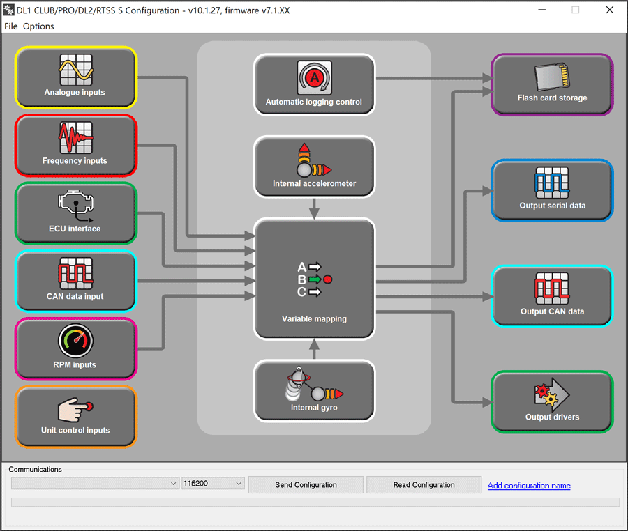
The software is broadly split in to the following sections:
INPUT CONTROL
- External inputs – Inputs connected to the analogue inputs or frequency inputs
- Unit control inputs - connecting inputs to control the unit, such as start/stop or add marker
- Internal sensors – built in sensors such as GPS, gyro, accelerometers
VARIABLE MAPPING - specifying where each channel of data comes from
OUTPUT CONTROL
- Output drivers - On/Off or PWM output drivers
- Flash card storage – what is stored to the memory card
- Output serial data – what data is transmitted on the serial port
When creating a configuration file, it is HIGHLY recommended that the unit is configured in this order:
- ECU interface
- Analogue inputs
- Frequency inputs
- RPM inputs
- Unit control inputs
- Gyro
- Accelerometer
- CAN input configuration
- Variable mapping
- Output Drivers
- Output Serial data
- Flash card storage
- Automatic logging control