Installing the SPEEDBOX
The installation instructions in this section apply to the standard SPEEDBOX, and the SPEEDBOX MINI.
Installation Checklist
The following checklist is designed to be a quick reference for connecting the system in day-to-day usage. It is recommended that the more detailed explanations of each step are read in their entirety before initially installing the unit.
- Ensure the power is disconnected.
- Secure the unit safely in the vehicle, taking careful note of the mounting orientation.
- Connect the supplied antenna to “GPS A (Main)” on the rear of the SPEEDBOX.
- Mount the antenna(s) on the vehicle roof – do not crush the cable in the doors or windows.
- Connect the power to a fused 9 – 30V DC supply (SPEEDBOX MINI 9 - 15V), e.g. a “cigarette-lighter” type plug, or other fused power supply.
Mounting the SPEEDBOX Base Unit
An engineering drawing of the SPEEDBOX is included here.
In order to give accurate speed and acceleration readings, the SPEEDBOX base unit should be mounted so that it is flat, level, in the correct orientation, protected from vibration, as close as possible horizontally to the antenna, and restrained from moving relative to the vehicle. These requirements are discussed further below.
Correct orientation of the unit is essential. The unit must be mounted with the direction of travel as shown by the arrows on the top of the unit. When mounted correctly the longitudinal acceleration will read positive whilst accelerating and negative whilst braking.
The unit should be mounted as flat and level as possible. The combined speed calculation will compensate for a mounting angle of up to 20° from level, but accuracy is slightly reduced, so for best accuracy mount as level as possible. Neither the raw 20Hz GPS position and speed outputs nor the angular measurements from the RTK option are sensitive to the mounting orientation or level.
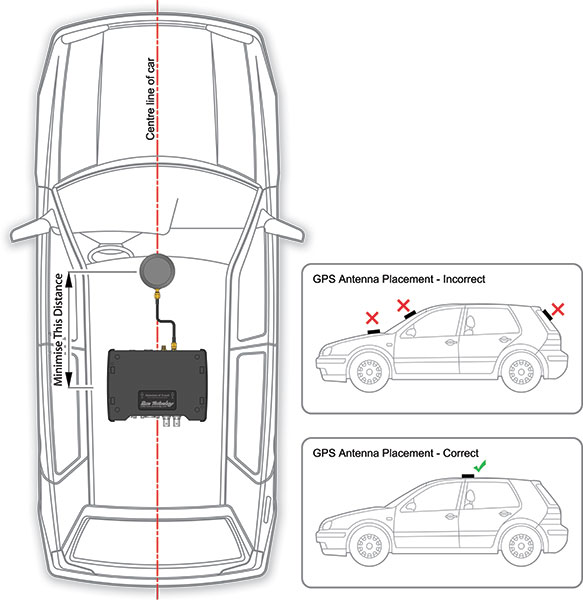
Figure 1. Mounting arrangement for standard SPEEDBOX using a single GPS antenna
The base unit should be mounted as close as possible to the GPS antenna in the horizontal plane, i.e. the best mounting location would be vertically below the GPS antenna (the rear antenna on the RTK system). This ensures that the accelerometers and the GPS antenna “see” the same velocity. In practice, it is not necessary to conform to this requirement if performing low-dynamic testing, or straight line testing. This constraint does however become important if using the combined speed output whilst performing hard cornering, particularly at low speeds.
The base unit should also be shielded from vibration as far as is possible. “Normal” levels of vibration are tolerated with no problem, but particularly harsh vibration may degrade the operation of the GPS receiver, resulting in either reduced accuracy or loss-of-lock.
The unit can be securely restrained in the required position, either by bolting it in place through the four 4.3mm diameter holes in the mounting brackets, or by using a secure locking tape such as “Scotch-Lock”.
Mounting and Connecting the GPS Antenna
The SPEEDBOX requires a 3.3V active antenna (supplied) which must be mounted in a position giving a good view of the sky. On top of the vehicle is recommended. Care should be taken not to crush the antenna lead with the vehicle window or door closure. In view of the importance of good GPS reception to the measurement accuracy we have provided detailed guidance for antenna mounting on our online knowledgebase here.
We recommend that you refer to this resource if in any doubt.
On the SPEEDBOX the antenna must be connected to "GPS A" on the rear of the base unit.
Setting up the SPEEDBOX Antenna Offset
For firmware newer than v3.7.3 a lever arm can be set up between the antenna location and the SPEEDBOX unit containing the accelerometers (SPEEDBOX-INS systems do not need to set this lever arm) the unit uses this information to model the dynamics of vehicle pitch to produce increased accuracy through braking tests that feature pitching movement either during or immediately prior to the test. This offset is optional, but is highly recommended for braking tests.
SPEEDBOX Antenna Offset option in v4.2.8 or later SPEEDBOX Configuration Utility Software
Note: Measurements shown are only an example, actual values must be measured from your installation.
Setting up the SPEEDBOX Measurement Offset - Firmware v3.7.3 and later
For firmware newer than v3.7.3 a measurement offset can be set up, allowing the SPEEDBOX unit to model the dynamics of the vehicle, referencing the measurement to a specific point on the vehicle, a separate component such as a laser barrier used for triggering a test, or a reference system for direct comparison. Configuring this function correctly results in increased accuracy.
SPEEDBOX measurement output offset in v4.2.8 or later SPEEDBOX Configuration Utility Software
Note: Measurements shown are only an example, actual values must be measured from your installation.
For both the SPEEDBOX lever arm and measurement offset, the locations are referenced to the SPEEDBOX unit. Measure the distances below, ahead (and right for INS units), using negative values for opposite directions, and input these into the configuration software (v4.2.8 or later).
Power
The SPEEDBOX requires a stable DC power supply, which must be in the range 9 – 30V (9-15V SPEEDBOX MINI). This should be connected to the cable loom assembly that is supplied with the SPEEDBOX via a fused connection to the vehicle. A 1A fast blow type fuse is recommended. Once connected to the power supply, the SPEEDBOX will automatically power up and commence its initialisation routine. The current consumption of the SPEEDBOX ranges from approximately 230mA @ 12V for the standard SPEEDBOX to 400mA @ 12V for the SPEEDBOX-INS. More current may be drawn during startup.
Unreliable power supplies are a common source of problems. In the event of any problems, please check the reliability of the power source or try an alternative supply in the first instance. The SPEEDBOX may also be powered from an external battery pack. If you require a battery pack, Race Technology keeps a wide selection in stock - please contact us with your requirements. Because of the current supply requirements, only rechargeable batteries should be used. Disposable cells are not suitable.