How to decode RPM using the Pass-by noise CAN raw data option
To successfully complete the pass-by noise R41/R51 procedure RPM is required to be measured during the test for almost all vehicles.
R51 (passenger vehicles/light goods vehicle) RPM is very straight forward as all manufactures must comply with the ISO 9141 protocol (OBD) making RPM available on the OBD connector for all vehicles. Therefor the Race Technology system is supplied with the correct cable to plug directly into the car. RPM is very much a �plug and play� solution for R51.
R41 (Motorcycles) is not so simple, motorcycles do not have a common protocol or common connector.
The Race Technology pass-by noise system has direct RPM inputs to take RPM from a pulse signal such as tacho feed, injector or even the high voltage level ignition system.
On modern motorcycles RPM will be available on the motorcycles CAN BUS. However, the CAN bus protocol varies from model to model as well as manufacture to manufacture. Vehicle manufactures will obviously have access to the information required to get the RPM but this information is not available for general use.
Race Technology has built up an extensive database of connections and protocol information. Before attempting to follow these instructions, contact us to find out what information we already have!
Step 1 � Locate the CAN bus
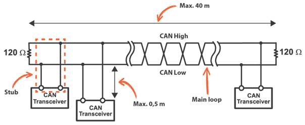
Below is a general diagram of a CAN bus. These 2 wires are the wires that need locating.
What is common and helps locate them are:
- Wires are twisted together (Stops interference)
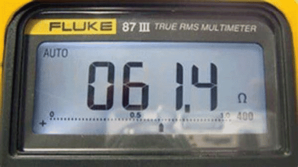
- A working CAN bus will have 60ohm resistance between CAN+ and CAN- (2x 120ohm in parallel)
Look for twisted wires and a convenient connector then use a multi-meter and check 60ohm (+/- 3ohm) is across the 2 wires with power switch off.
Example
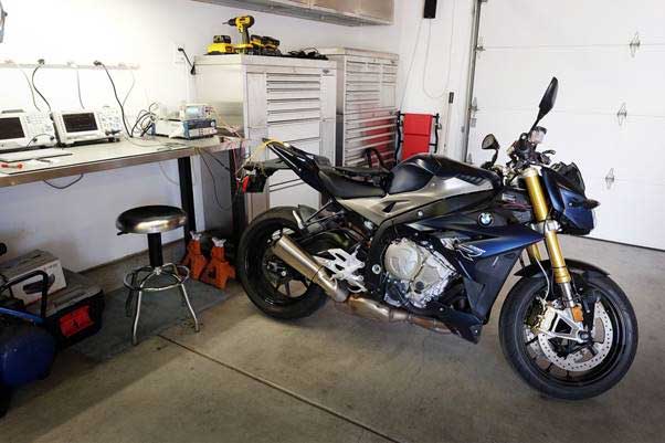
Here is an example for the BMW S1000R
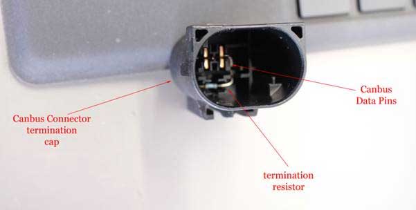
The BMW S1000R motorcycle has a convenient CAN bus termination connector. Inside this connector is the required CAN bus 120ohm termination resistor.
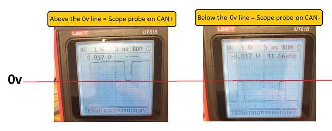
Step 2 � Work out which is CAN+ and CAN-
For this step an oscilloscope is required.
- Connect the scope onto the CAN probe onto 1 wire ground clip onto the other. Adjust the scope until a clear scope trace is displayed.
- CAN trace going above 0v line = probe on CAN+
- CAN trace going below 0v line = probe on CAN-
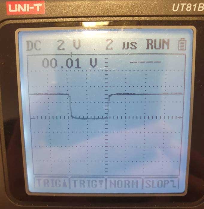
Step 3 � Work out the baud rate
The baud rate is how fast the data is transmitted. The baud rate will be either 1Mbit/s, 500kbit/s or 250kbit/s. This means the minimum time base per bit will be:
a) 1us (1s/1000000bit/s)
b) 2us (1s/500000bit/s)
c) 4us (1s/250000bit/s)
Adjust the oscilloscope and determine the minimum base time on the signal. The screen shot below the answer is 4us (250kbit/s)
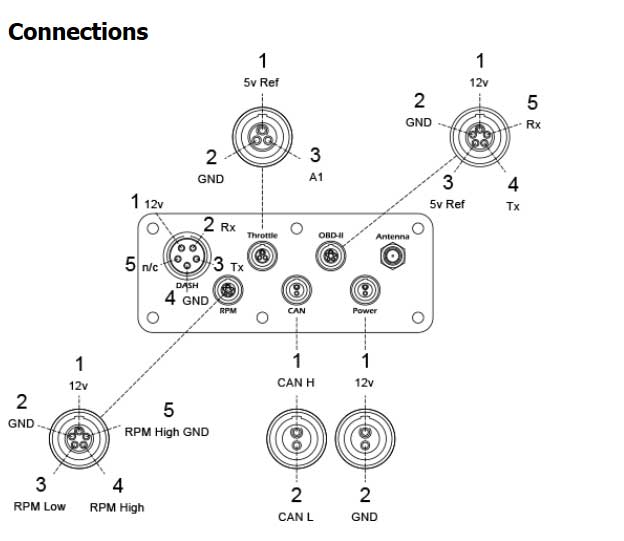
Step 4 - Connect the Pass-by noise system to the vehicles CAN bus using the supplied CAN lead.
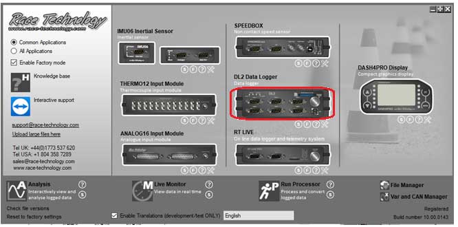
Step 5 - Configure the Pass-by noise system
- Set CAN bus baud rate and enable CAN RAW
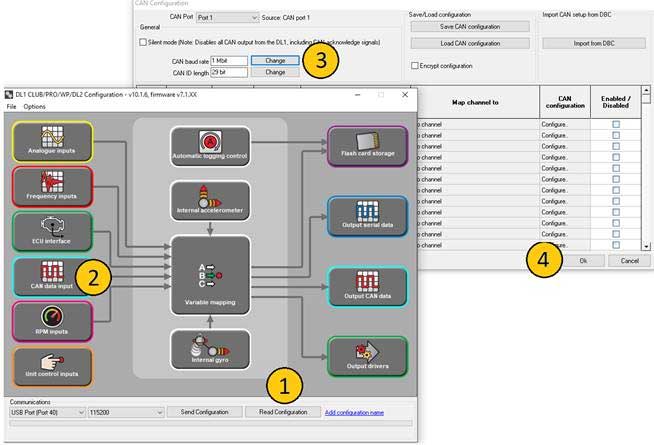
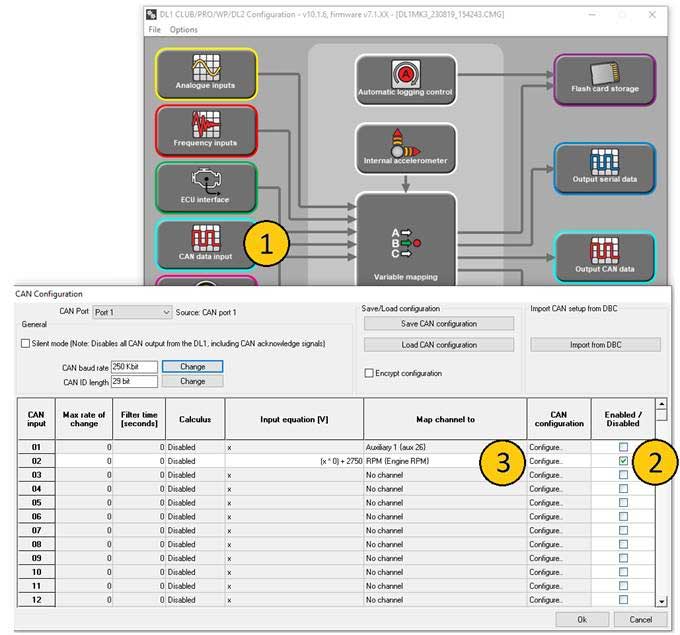
- Open the configuration software shown below
IMPORTANT: Read back the configuration before editing
Open the CAN data input and set the CAN baud rate to determined baud rate in step 3.
1) Read back configuration
2) Open CAN input configuration
3) Set baud rate
4) Click ok
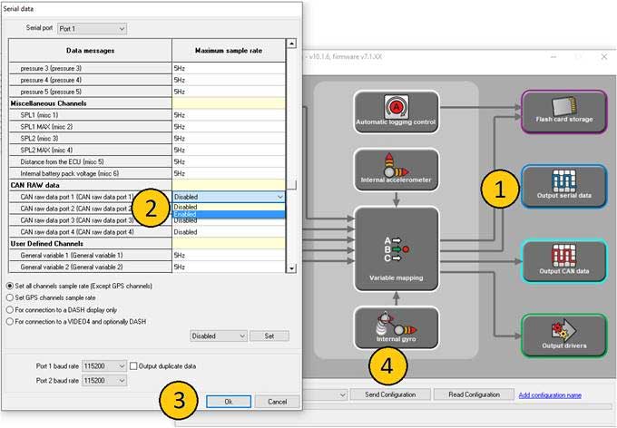
Enable CAN raw to be transmitted. By default this is switched off as it is likely to overload the modem. Once RPM signal is fully configured remember to go back and disabled the CAN raw from the serial port.
1) Open Output serial data
2) Find CAN raw data port 1
3) Click OK
4) Send configuration back to unit
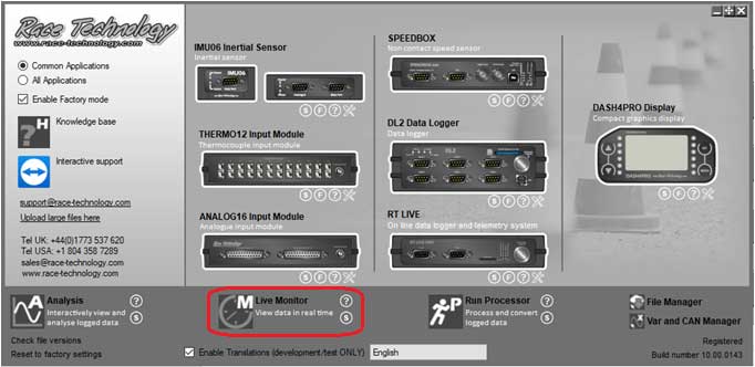
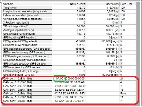
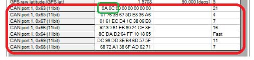
Step 6 - View the RAW CAN data using the live monitor software. Open the live monitor and connect to the system
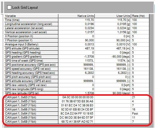
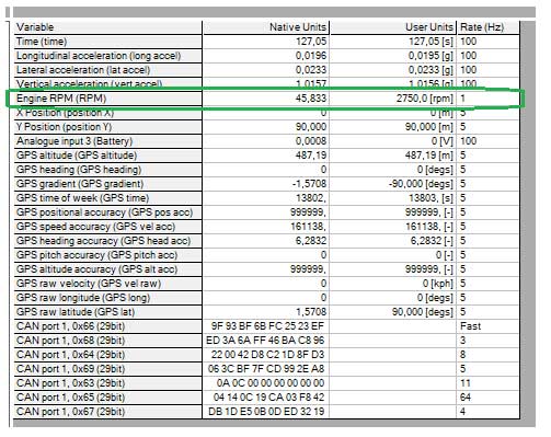
If everything is connected and configured correctly you will notice RAW CAN data at the bottom of the standard available variables as shown below.
This is the raw data for all devices on the motorcycles CAN bus. RPM in most cases will be 2 bytes. If you are not familiar to this then with the engine off, open and close the throttle and try to identify which message is throttle. This is often obvious and will be a good way to learn how to spot the required CAN message
Start the engine and look for 2 bytes that correlate with revving the engine.
Step 7 - Configure the RPM
1) Open CAN data input configuration
2) Enable RPM
3) Click configure
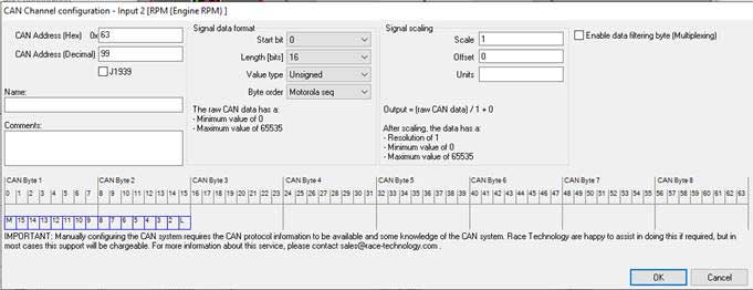
Set the configuration to decode the identified RPM bytes.
Send configuration back to unit and you will now be able to see the RPM in the software.
Once complete disable CAN raw on serial port and save a copy of the configuration for future use.