RTK
RTK settings can only be set on a SPEEDBOX unit which is equipped with the RTK option, including the dual antenna INS option.
NOTE: After changing any RTK settings, the unit should be re-booted in order to ensure correct operation before commencing any measurements.
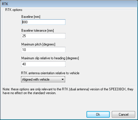
Baseline [mm]:
This is the distance between the centres of the two RTK antennas.
For antenna strips supplied by Race Technology where the distance between the antennas is fixed this should normally be set to the default value of 800mm, which is the distance between the antennas on all currently available Race Technology antenna assemblies. The only exception to this is if the flexible magnetic mounting antenna strip is placed on a significantly curved roof, in which case the direct distance between the antennas may be less than the 800mm path distance. In this case, a more accurate direct distance can either be measured manually, or experimentally determined by logging the measured baseline distance stationary with a good clear view of the sky over a minimum period of several hours and taking the average valid distance.
When using two discrete antennas, it is recommended to place the antennas between 700mm and 1m apart, and the distance between the centre of the two antennas must then be measured as accurately as possible and entered in this field. Setting the antennas less than 700mm apart may result in degradation of accuracy. Using a distance greater than 1m may result in the unit being unable to acquire RTK lock due to the search space becoming too large. Please contact Race Technology for advice should you wish to use a baseline distance greater than 1m.
Baseline Tolerance [mm]:
This is the tolerance between the specified baseline distance (above) and the baseline distance measured by the solution within which the solution will be regarded as valid. This value encompasses errors in the baseline measurement, uncertainties in the antenna phase centre location, and noise in the RTK solution, and hence must be set with some care. The default value is 50mm for the SPEEDBOX-RTK, and 25mm for the SPEEDBOX-INS. We do not recommend increasing either of these values. The value for the SPEEDBOX-RTK may be reduced in order to lessen the probability of false lock when stationary. However, reducing the value will increase the likelihood of losing a valid lock due to noise. 25mm is a realistic lower limit for acceptable performance.
Maximum pitch [degrees] and Maximum slip relative to heading [degrees]:
These are respectively the maximum pitch angle and the maximum slip angle which the vehicle is expected to see during operation. Setting realistic limits on these will aid the system when acquiring a moving RTK lock both in ensuring that the lock is valid, and minimising the time required to acquire or re-acquire a moving RTK lock by minimising the search space. For applications with minimal slip angles, such as standard highway driving, the slip angle can be reduced from the default. For applications where very large slip angles may be expected, such as drift racing on ice, the slip angle may need to be increased from the default.
RTK antenna orientation relative to vehicle:
The standard orientation of the RTK antenna strip or antennas is in-line with the vehicle, in which configuration it measures yaw and pitch. Using this option, it is possible to mount the antenna strip across the vehicle, in which case the measured output will be yaw and roll. The setting of this option must match the physical installation of the antenna strip or the unit will be unable to obtain an RTK lock. The available options are shown below:
The specified rotation is that of the antenna strip with respect to the vehicle. For the default "aligned with vehicle" case, the master antenna connected to GPS 1 is at the rear of the vehicle, and the secondary antenna connected to GPS 2 is at the front of the vehicle. For the "rotated 90° anti-clockwise" case, GPS 1 is on the right of the vehicle, and GPS 2 on the left. For the "rotated 90° clockwise" case, GPS 1 is on the left of the vehicle, and GPS 2 on the right. This is summarised in the table below:
| Alignment Option | GPS 1 location | GPS 2 location | Output |
| Aligned with vehicle | Rear | Front | Yaw and pitch |
| Rotated 90° anti-clockwise | Right | Left | Yaw and roll |
| Rotated 90° clockwise | Left | Right | Yaw and roll |