Set up the DL1 for Analogue Gear Sensors
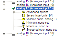
1. Open the variable manager and select the analogue input which is connected to the gear sensor, if it is connected to a DASH2 then this will typically be analogue input 17:
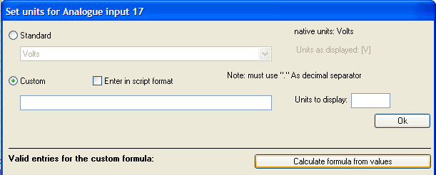
2. Click on the "sensor type/units" node and then select the custom definition:
3. Click on the "Calculate formula from values" button.
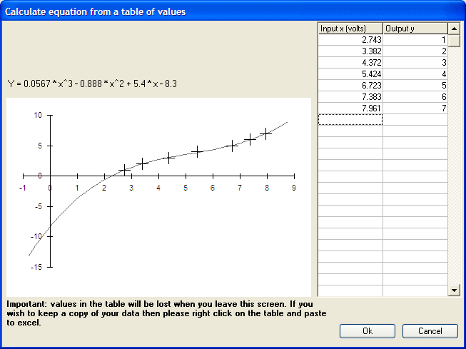
4. Follwing window will be opened. Enter the voltages on the input side and the gear number on the output side:
5. You will be taken back to the equation when you click "ok", in this case we've got an equation of:
(0.05666592) * x^3 + (-0.88773582) * x^2 + (5.39785867) * x + (-8.30177407)
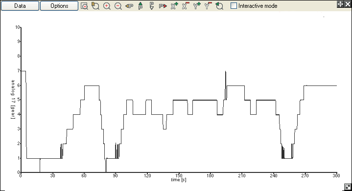
This is fine, but it we use this conversion directly the gear indicator appears to be a little "noisy":
6. So edit this to make sure that we get a integer or whole number answer by adding:
floor ( ..... + 0.5)
so the whole equation now reads:
floor ( (0.05666592) * x^3 + (-0.88773582) * x^2 + (5.39785867) * x + (-8.30177407)+ 0.5)
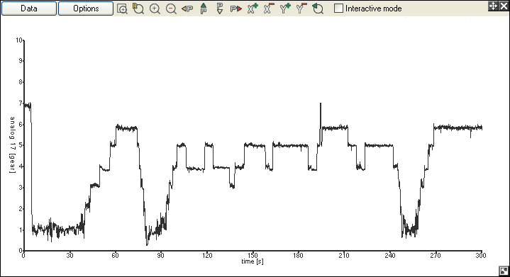
Note that you can't see the whole equation at the same time due to the size of the input box. With this done we have a direct reading of the gear position:

