Analogue and RPM input
The analogue and RPM inputs are factory fitted optional features of the VIDEO4 and have been specified at the time of ordering.
If the analogue and RPM inputs are fitted to the VIDEO4, then the analogue inputs can be used to log data from external sensors, for example you can connect these inputs to temperature and pressure sensors. These inputs accept a voltage in the range of 0 to 5v, making them compatible with all standard Race Technology sensors. The RPM input accepts a “low level signal”, that nominally goes between 0 and 12v, this is typical of the type of signal that comes from an ECU. If it’s required to connect to a “high level signal”, for example from an ignition coil then it is essential to use an RPM conditioner, more details are available about this here.
For general information about connecting RPM and where to take a signal from, there is more information here.
For general information about connecting analogue sensors from other manufactures, please read the information here.
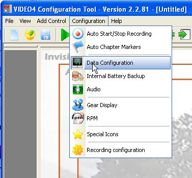
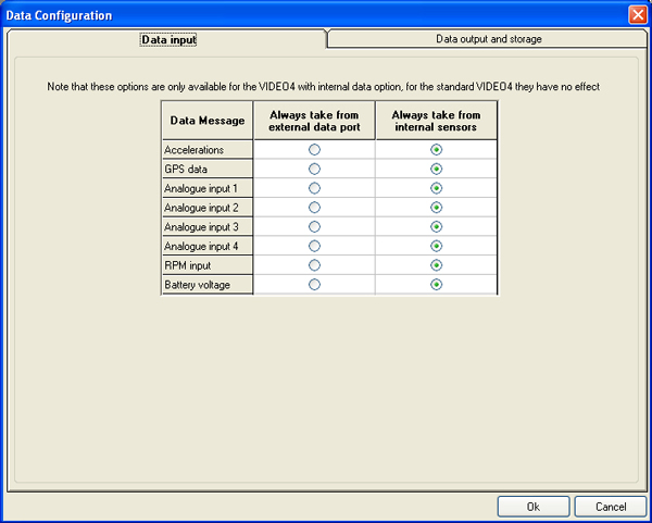
By default the VIDEO4 will take data from it’s external sensors when it is available, however in some more specialist configurations it might be required to configure where data is taken from. This configuration is set in the “VIDEO4 Configuration Tool”, the “Configuration” -> “Data Configuration” menu.
There are 2 options that are available here. The normal option is to take data from the internal sensors, however as an alternative you can force the VIDEO4 to take the data from the external data port. A typical application of this might be if you want to take RPM from an ECU adapter, instead of the built in RPM input.
Powering Race Technology sensors from the VIDEO4
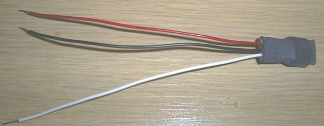
Please note that nearly all sensors supplied by Race Technology are designed to be run from a regulated 5v power supply, however the VIDEO4 doesn’t have a 5v reference output from the unit. To allow standard RT sensors to be used with the VIDEO4 is required that you use a separate 5v regulator. If you have bought the VIDEO4 and sensors from Race Technology then a suitable regulator will have been automatically included as part of the order, if you don’t have one then please contact Race Technology directly and we will arrange one to be sent to you. The regulator looks like this:
The 3 wires on the unit are:
- Red. This is the 12v input to the regulator
- Black. This is the ground connection
- White. This is the 5v output that goes to the sensors
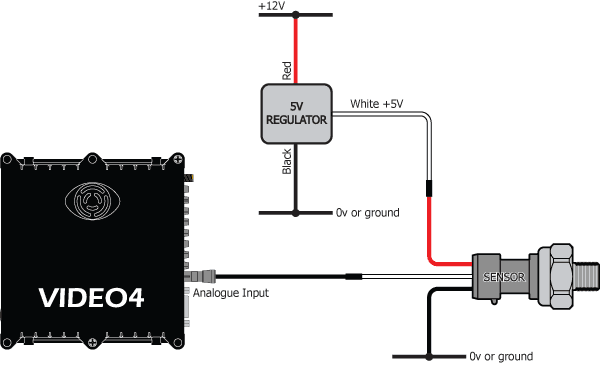
The regulator should be connected up as shown in the diagram below:
Very important: This regulator is only suitable for supplying a relatively small amount of current to our sensors and is rated at a maximum of 100mA.
Note:
The “voltage and temps” switch controls all voltage and temperature channels. If this is left as “internal sensors” then it will record the VIDEO4 internal box temperature, as well as its input voltage and battery voltage when available.
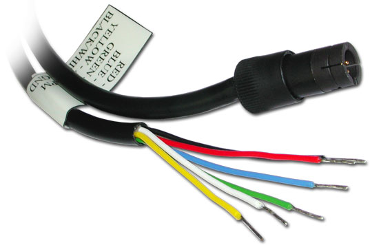
Supplied with this option is a cable for you to connect the analogue/RPM signals to the VIDEO4 connector. The cable is approximately 1m in length, with a VIDEO4 connector on one end, and stripped and tinned bare wires on the other end. The colour coded wires connect to the inputs as follows:
Red = A1
Blue = A2
Green = A3
Yellow = A4/RPM
Black/white = GND

