Call me back | My basket | Checkout | Add to email list

     You are here: Website » Knowledge base

« back to website

Connections / DL2

DL2 Connections

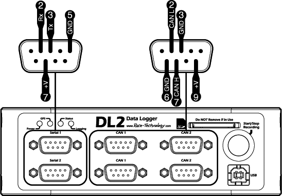
Front view


Serial ports 1 and 2

9 way D-type male connector

Pin Name Description
2 Rx Receive
3 Tx Transmit
5 GND GND
7 +V Power in/out


CAN ports 1-2

9 way D-type male connector

Pin Name Description
2 CAN L CAN port low
3 GND CAN port GND
6 GND CAN port GND
7 CAN H CAN port high
9 +V Power in/out


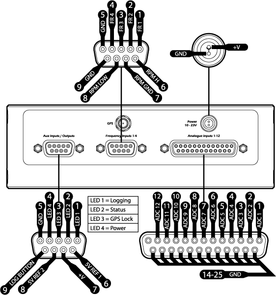
Rear view


Aux Inputs/Outputs

9 way D-type male connector

Pin Name Description
1 LED 1 Logging LED
2 LED 2 Status LED
3 LED 3 GPS Lock LED
4 LED 4 Power LED
5 GND GND
6 5V REF 1 0.5A Reference output 1
7 +V Power in/out
8 5V REF 2 0.5A Reference output 2
9 LOG BUTTON Switch to GND


Frequency Inputs 1-4

9 way D-type male connector

Pin Name Description
1 FR 1 Frequency in 1
2 FR 2 Frequency in 2
3 FR 3 Frequency in 3
4 FR 4 Frequency in 4
5 GND Power ground
6 RPM H High level RPM input
7 RPM GND High level RPM ground
8 RPM LOW 5-15v Trigger - ECU or Tacho use
9 GND Power ground


Power Connector

Name Description
+V Power Input
GND Power Ground


Analogue inputs 1-12 Outputs 1-4

25 way D-type socket

Pin Name Description
1 ADC 1 0-25v 12 bit analogue input
2 ADC 2 0-25v 12 bit analogue input
3 ADC 3 0-25v 12 bit analogue input
4 ADC 4 0-25v 12 bit analogue input
5 ADC 5 0-25v 12 bit analogue input
6 ADC 6 0-25v 12 bit analogue input
7 ADC 7 0-25v 12 bit analogue input
8 ADC 8 0-25v 12 bit analogue input
9 ADC 9 OUT 1 0-25v 12 bit analogue input, Output 1
10 ADC 10 OUT 2 0-25v 12 bit analogue input, Output 2
11 ADC 11 OUT 3 0-25v 12 bit analogue input, Output 3
12 ADC 12 OUT 4 0-25v 12 bit analogue input, Output 4
14 - 25 GND Signal ground
Page last modified on September 11, 2018, at 01:47 PM