|
Call me back |
|

You are here: Website » Knowledge base
|
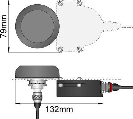
InstallingTheSPEEDBOX / INSSingleAntennaSingle Antenna INS InstallationThe SPEEDBOX base unit should be mounted inside the vehicle. The base unit can be mounted in any orientation for the SPEEDBOX INS, since the INS system takes all inertial measurements from the antenna assembly. The base unit should be isolated from excessive vibration, and the supplied power cable should be connected to a power supply between 9 and 30V (9-15V if SPEEDBOX MINI). Power consumption is approximately 0.4A @ 12V for the INS system, but some additional capacity is required at startup. The antenna assembly should then be mounted on the roof of the vehicle in the correct orientation, close to either the front or side of the roof, not in the middle. Further details are shown below. Once the base unit and antenna assembly have been correctly fitted, they must be connected using the supplied cable. This cable contains both the data cable for the IMU and the GPS antenna cable. The routeing of the cable from the base unit to the antenna assembly should avoid as far as possible any sources of RF interference, in particular components of the vehicle ignition system, telemetry or radio systems, and in some cases video camera systems. The data cable from the IMU to the SPEEDBOX base unit connects to the antenna assembly at one end with a “Deutsch” connector and to the “Expansion” port of the SPEEDBOX base unit at the other end with a Lemo connector. Note that the data cable must be connected prior to switching on the INS system in order for the antenna assembly to be correctly detected – if the power is supplied prior to plugging in the IMU cable then the SPEEDBOX will flash an error code to indicate that the IMU is not detected. In this case it is simply necessary to power-cycle the unit after plugging in the IMU cable. The GPS cable connects to the GPS antenna on the antenna assembly, and to the GPS connection labelled “RF1” on the SPEEDBOX base unit. Please refer to figure 1 below for clarification.  Figure 1. Single antenna GPS connection to SPEEDBOX base unit. Single Antenna INS Mounting Instructions The general dimensions of the Single Antenna Tactical unit are shown above. See below for mounting options and how the unit's layout changes with each installation option. There are 2 mounting options available for the single antenna INS: temporary external, or permanent internal mounting. The choice between external and internal mounting must be made when ordering, since different hardware is required for each case. The mounting instructions for both options are presented below. Inertial Sensor Point Of ReferenceAll inertial measurements are referenced to the following point in the single antenna INS unit, this point is known as the point of percussion: 
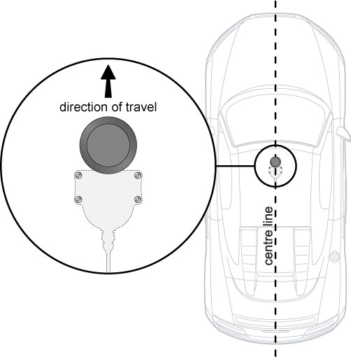
1. Temporary external mounting.This mounting option is ideal for testing of multiple different vehicles where rapid fitment and removal is required, or in situations where it is not possible to drill any holes for permanent fixing. For the temporary mounting, the antenna assembly is mounted to the roof magnetically. The unit is supplied pre-bolted to a stainless steel plate containing 3 magnetic mounting points. The magnets are covered in a thin membrane to prevent damage to paintwork. This membrane should be periodically inspected before fitment, and renewed if required. The complete antenna and magnetic mounting assembly is shown in figure 2. The direction of travel is also shown. It is crucial that the correct direction of travel is adhered to; the cable attachments must be at the rear of the assembly. The rear-most mounting point is fitted with a securing strap for the IMU cable; this should always be used as shown in figure 2 otherwise flexing movement of the cable can damage the connector internally. Note that the GPS cable (the thinner one) runs above the securing strap - please refer to figure 2 for clarification. IMPORTANT!! To keep vibration effects to a minimum, mount the unit close to either the front, rear, or side of the roof where the roof is least flexible. Additionally the unit should be mounted at no more than 20 degrees from the horizontal. 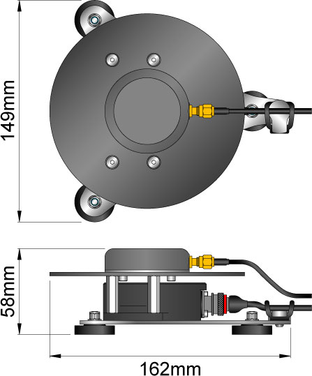 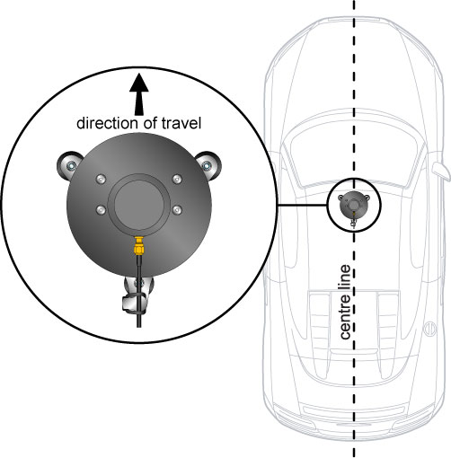 Figure 2 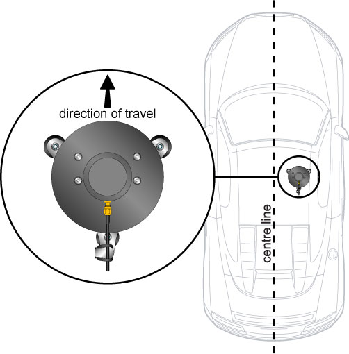 Figure 3 The magnetic mounting assembly has been tested on road vehicles up to normal fast road speeds (~130kph) and on the track up to moderate race speeds (~170kph), and has proved absolutely secure at those speeds. At higher race speeds or with extreme vibration the security of the mounting should be initially assessed with a security tether fitted, and it may be that the permanent mounting option may be required.
2. Permanent internal mountingThis is the ideal option for a permanent install where the minimum obstruction to airflow is required. The downside is that it involves the most drilling into the vehicle. This mounting option must be specified when purchasing the unit, since the hardware supplied is different, and the SPEEDBOX-INS must be factory configured to expect this mounting orientation. In this mounting option, the GPS antenna is the only component mounted on the outside of the vehicle, and the IMU assembly is mounted upside-down on the inside of the vehicle roof. The distance between the GPS antenna and the IMU assembly must be kept as close to the template shown as possible both horizontally and vertically, since this “lever arm” distance is compensated for in the firmware when this mounting is specified, and any deviation will result in an uncompensated lever-arm affect, which is undesirable. The hardware and direction of travel for this mounting option are shown in figure 4 below, and the mounting hole dimensions are shown in figure 5. Note also that it will be necessary to secure the main IMU cable sufficiently to avoid flexing movement damaging the connector internally - simply using a cable tie to secure to a fixed location within 30cm of the connector would be sufficient, the closer the tie down is to the connector the better. IMPORTANT!! To keep vibration effects to a minimum, mount the unit close to either the front, rear, or side of the roof where the roof is least flexible.
Figure 4
Figure 5 Using multiple IMU units with a single SPEEDBOXThe calibration data for the INS sensor is stored in the roof mounted unit. As such it is possible to buy mutliple extra INS sensors to be fitted to vehicles and operate with a single SPEEDBOX control unit. Using the SPEEDBOX-INS auto-levelling optionThe single antenna SPEEDBOX-INS includes an option to auto-level the antenna in software. This can be used to compensate for small offsets of pitch and roll from the horizontal when it is impossible to mount the antenna perfectly level relative to the vehicle. It is only recommended to use this to compensate for offsets up to approximately 10 degrees in either axis; beyond this a more level mounting should be sought. Using the auto-levelling is entirely optional; it is not necessary to use it at all. The advantages to using it are that when levelled correctly the output pitch and roll will have no constant offset due to the mounting orientation relative to the vehicle. The sensitivity on the lateral and longitudinal accelerometers will also be slightly affected. The auto-levelling system works as follows. When a specific command is sent to the SPEEDBOX-INS over the serial port, the SPEEDBOX-INS will read and average a short period of accelerometer data, and will calculate the pitch and roll angles based on this measurement. The levelling command should be sent only when the vehicle is level and stationary, in order that the only offset measured is that of the antenna relative to the vehicle. The levelling offsets thus acquired are stored in non-volatile memory for future use, and thus it is only necessary to re-send the command when the antenna assembly has been moved relative to the vehicle. The levelling command will calculate and store an offset regardless of whether the offset is to be used or not. Whether the offset is used is a configurable option. When enabled, the stored pitch and roll offset is used to correct the sensed data in all six axes immediately following measurement, and prior to the measurements being incorporated into the INS mechanisation. Hence both the raw measurement output (accelerations, gyro rates) and the INS system output (attitude) are corrected. The levelling command can be sent in one of two ways. First, ensure that the vehicle is level and stationary, and the antenna is mounted as required. Then, either:
In both instances, the SPEEDBOX-INS will flash the blue trigger LED rapidly 3 times to confirm that the levelling calculation has been run, and then store the results. If the use of auto-levelling is enabled (see next section) then it can be verified using the Lite Monitor or CAN output that the longitudinal, lateral and vertical accelerations are 0, 0 and -1g respectively. To enable or disable the use of the stored levelling data, start the configuration software, connect to the SPEEDBOX-INS, and open the INS Options tab. Either tick or un-tick the checkbox labelled "use roll and pitch autolevelling" as required (figure 8). Note that the last calculated levelling data is still retained in memory even when this checkbox is unticked, so that it can be used again in future if required. IMPORTANT: Although the offset will correct for errors in pitch and roll mounting angles, if the yaw mounting on the vehicle is not correct then the accelerometer readings will be affected. As an extreme example, if the sensor is mounted at 90 degrees to the direction of travel, the offsets can be zero but any acceleration force will show up as cornering force and vice-versa. 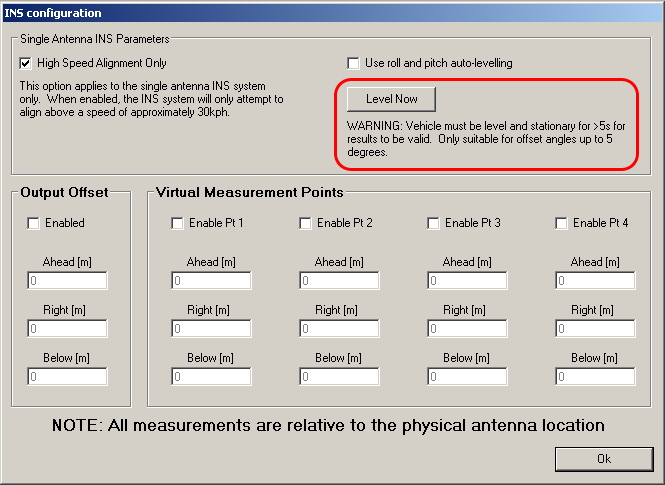 Figure 7: “Level Now” button
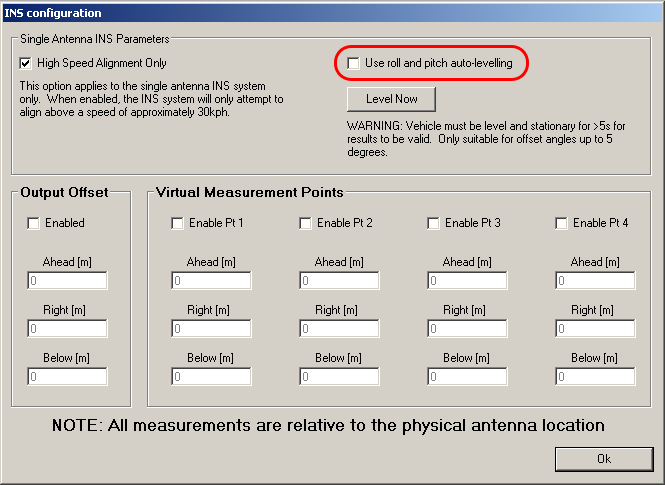 Figure 8: Checkbox to enable or disable the use of auto-levelling data. Setting up the SPEEDBOX Measurement OffsetA measurement offset can be set up allowing the SPEEDBOX unit to model the dynamics of the vehicle, referencing the measurement to a specific point on the vehicle, a separate component such as a laser barrier used for triggering a test, or a reference system for direct comparison. Configuring this function correctly results in increased accuracy. 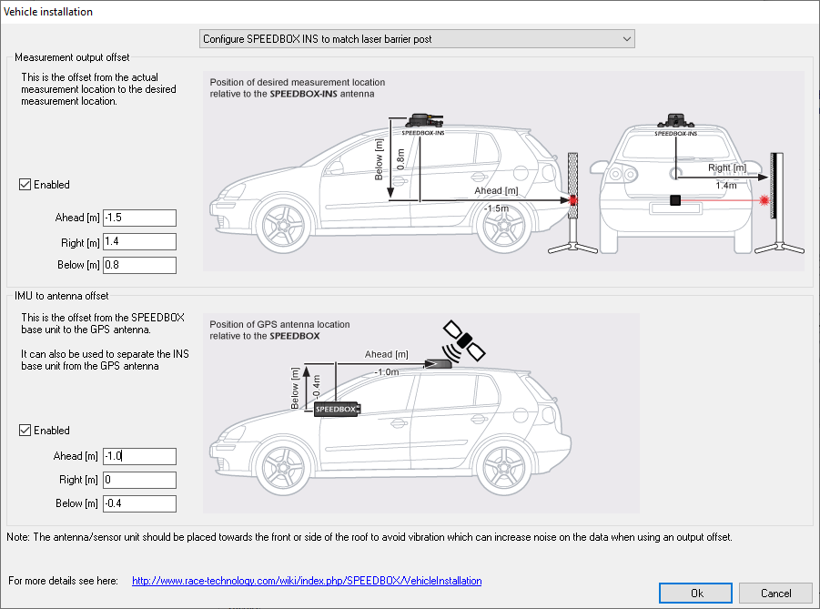 SPEEDBOX-INS measurement output offset. For the SPEEDBOX-INS measurement offset is taken from the INS antenna assembly to the offset point. Measure the distances below, ahead and right, using negative values for opposite directions, and input these into the configuration software. Notes on using the output offset: Using an output offset will give increased noise on the accelerometer readings due to the vibrations on the roof being picked up by the gyros. As such, when using output offsets it is vitally important that the sensor is mounted away from the centre of the roof to reduce vibration effects. To check whether noise on the accelerometer readings is real or due to the output offset, test on the vehicle with the output offset enabled and disabled and compare the results. If noise is still an issue despite mounting on a stiff area of the roof, then consider separating the IMU from the antenna and mounting it closer to the vehicles COG. Then enable the IMU to antenna offset in the configuration software. When using this mode it is important that the offset measurements are as accurate as possible to avoid errors in the output readings. |