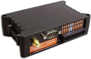
DL1 CLUB Connector details
Rear View
| PIN
| DESCRIPTION
|
| 1
| CAN L - Low connection for CAN interface
|
| 2
| RX1 - Serial port 1 Data In
|
| 3
| TX1 - Serial port 1 Data Out
|
| 4
| TX2 - Serial port 2 Data Out
|
| 5
| GND
|
| 6
| RX2 - Serial port 2 Data In
|
| 7
| +12v Out ( 250 mA limit)
|
| 8
| CAN H - High connection for CAN interface
|
| 9
| N/C
|
| LABEL
| DESCRIPTION
|
|
| A1
| 0-25v 12-Bit analogue input
| In
|
| A2
| 0-25v 12-Bit analogue input
| In
|
| A3
| 0-25v 12-Bit analogue input
| In
|
| A4
| 0-25v 12-Bit analogue input
| In
|
| A5
| 0-25v 12-Bit analogue input
| In
|
| A6
| 0-25v 12-Bit analogue input
| In
|
| A7
| 0-25v 12-Bit analogue input
| In
|
| A8
| 0-25v 12-Bit analogue input
| In
|
| A9
| 0-25v input, low side output 0.5A Max
| In/Out
|
| A10
| 0-25v input, low side output 0.5A Max
| In/Out
|
| A11
| 0-25v input, low side output 0.5A Max
| In/Out
|
| A12
| 0-25v input, low side output 0.5A Max
| In/Out
|
| rL - RPM Low Level
| 5-15v Trigger - ECU or Tacho Use.
|
|
| GND
| System and sensor ground
|
|
| rH - RPM High Level
| 1KHz HT Input - See Connecting RPM
| In
|
| rG - RPM High Level Ground
| See Connecting RPM
| In
|
| F1
| 100K Pull Down Included. 5-12V I/P >2KHz Max.
| In
|
| F2
| 100K Pull Down Included. 5-12V I/P >2KHz Max.
| In
|
| F3
| 100K Pull Down Included. 5-12V I/P >2KHz Max.
| In
|
| F4
| 100K Pull Down Included. 5-12V I/P >2KHz Max.
| In
|
| +5v1
| 500mA Max reference output
| Out
|
| +5v2
| 500mA Max reference output
| Out
|
| +12v
| 9-24v power input
| In
|
| GPS RF +3.3v
| GPS Antenna Connection (3.3v)
|
|
When the CAN interface or second serial port options are ordered for the DL1 CLUB the following breakout cable will also be supplied, to enable easy connection:
"WARNING": To avoid any possible damage to the car paintwork, please take care when mounting magnetic GPS antennas. In particular make sure that there are no dust or grit under the antenna. In some cases it maybe required to add additional protection to the paintwork prior to mounting the antenna to avoid damage.