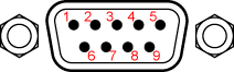
Connector details
Serial port 1
9 way D-type male connector
| Serial connector pin out details
|
| Pin
| Function
|
| 1*
| ADC 4
|
| 2
| Receive
|
| 3
| Transmit
|
| 4*
| ADC Ground
|
| 5
| GND
|
| 6*
| ADC 2
|
| 7
| Power in +12v supply
|
| 8*
| ADC 1
|
| 9*
| ADC 3
|
* note that ADC pins are only available on the DB9 for the SPEEDBOX MINI
Serial port 2
9 way D-type male connector
| Serial 2 connector pinout details
|
| Pin
| Function
|
| 1
| NC
|
| 2
| Receive
|
| 3
| Transmit
|
| 4
| Secondary Transmit*
|
| 5
| GND
|
| 6
| Secondary Receive
|
| 7
| Power in +12V supply
|
| 8
| NC
|
| 9
| NC
|
*The secondary transmit and receive ports are not implemented presently, these pins should be left as NC.
Pulse output
BNC 50 ohm connector
| Pulse output connector details
|
| Centre
| Signal
| 0=0V
1=5V
max 5mA
|
| Shield
| GND
|
|
Trigger input
BNC 50 ohm connector
| Trigger Input details
|
| Centre
| Signal
| <O.5V = low.
high => 2.1V
Internal pullup to 2.5V
|
| Shield
| GND
|
|
NOTE: There is an internal debounce on the trigger input which means that only one edge will be detected during the debounce period (50ms). As such, when triggering on thin laser barrier strips or short button presses it is important to trigger on the first edge which will be seen, otherwise the trigger signal can be missed.
CAN port
9 way D-type male connector. If two CAN ports are present on the front of the unit then they are internally connected in parallel, this makes connecting termination much simpler.
| CAN port connector pinout details
|
| Pin
| Function
|
| 2
| CAN L
|
| 6
| GND
|
| 7
| CAN H
|
| 9
| 12v
|
| Termination
| None Fitted
|
| Dominant bit
| >2.5V difference
|
| Recessive bit
| <0.9V difference
|
NOTE: No internal CAN termination is fitted within the SPEEDBOX, It is essential that the user fits appropriate termination if required. In general, if the SPEEDBOX is at one end of a two node CAN network with a CAN logging device at the other end, then the SPEEDBOX will need to be fitted with a 120Ω resistor between CAN H and CAN L in the cabling used to attach it to the network
Analogue input/output
SPEEDBOX in CNC machined case - up to 2019.
LEMO 4 pin connector part number FGG.0B.304.CLAD52Z
| Analogue connectors pinout details
|
| Pin
| Function
| Voltage range
|
| 1
| Signal ground
|
|
| 2
| Input/Output
| -10 to + 10 output, 0-15V input
|
| 3
| 12V sensor supply
|
|
| 4
| Sensor supply GND
|
|
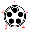
LEMO 5 pin connector part number FGG.0B.305.CLAD52Z
SPEEDBOX in Diecast Case (2019 onwards)
| Analogue connectors pinout details
|
| Pin
| Function
| Voltage range
|
| 1
| Signal ground
|
|
| 2
| Output
| -10 to + 10 output
|
| 3
| 12V sensor supply
|
|
| 4
| Sensor supply GND
|
|
| 5
| Input
| 0-15V input
|
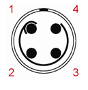
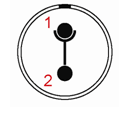
Power connector
LEMO 2 pin connector part number FGG.0B.302.CLAD52Z
| Power Connector pinout details
|
| Pin
| Function
|
| 1
| +ve
|
| 2
| GND
|
9 - 15V for SPEEDBOXBOX MINI
9 - 30V for SPEEDBOXBOX
Antenna 1 and 2
SMA 3.3V feed to antennas. On the standard SPEEDBOX and the SPEEDBOX-INS Single Antenna only �GPS A (Main)� is connected. On the SPEEDBOX-INS Dual Antenna (and older dual antenna SPEEDBOX systems) RF 1 is connected to GPS A (Main) and is the rear antenna on the vehicle, RF 2 is connected to GPS B and is the front antenna on the vehicle.
INS Sensor Port - LEMO 1B
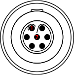
|
| 7 way LEMO 1B connector
|
| INS Sensor port connector pin out details
|
| Pin
| Function
| Voltage range
|
| 1
| GND
|
|
| 2
| +16V Supply
|
|
| 3
| SPI Chip Select
| 0-5V
|
| 4
| SPI Out
| 0-5V
|
| 5
| SPI In
| 0-5V
|
| 6
| SPI Clock
| 0-5V
|
| 7
| External Interrupt
| 0-16V transition level approx 1V, internal pullup
|
INS - Expansion port (early DB9 Type)
|
| 9 way D-type male connector
|
| Expansion port connector pin out details
|
| Pin
| Function
| Voltage range
|
| 1
| SPI clock
| 0-5V
|
| 2
| SPI in
| 0-5V
|
| 3
| SPI out
| 0-5V
|
| 4
| SPI chip select
| 0-5V
|
| 5
| GND
|
|
| 6
| External GPIO
| 0-5V
|
| 7
| +16V supply
|
|
| 8
| Time pulse output
| 0-5V
|
| 9
| External interrupt
| 0-16V transition level approx 1V,
internal pullup
|