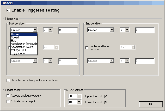
Triggers
The outputting of test data from the SPEEDBOX MINI can be triggered either based on a speed, the vehicle coming to a halt, lateral or longitudinal acceleration, a voltage input or one of the two hardware triggers, one hardware trigger is accessed through the bottom BNC connector on the front panel (trigger 1), and the other is accessed through the expansion connector (trigger 2). Triggers can be used either individually or as a set of two using a logical AND or OR condition. Whilst a triggered test is in progress, the blue LED on the SPEEDBOX lights to indicate this.
Speed trigger
Triggering based on speed can be set either for starting above or below a trigger speed, the required speed can be set in m/s, kph, mph, or knots
Halt trigger
Triggering based on the vehicle coming to a halt is a special case condition based on a combination of measured speed and acceleration, designed to give an accurate trigger for the moment the vehicle comes to a complete halt.
Acceleration trigger
Triggering based on either the longitudinal or lateral acceleration can be set to start above or below a set limit, the limit is set in either g or m/s^2. Accelerometers are sampled at 200Hz, as a result there is up to 5ms latency when triggering on accelerometer values.
Voltage trigger
Any of the four analogue inputs can be used for triggering starting or stopping of a test, the condition is set in terms of the input being above or below a target voltage value. Analogue channels are sampled at 200Hz, as a result there is a maximum of 5ms latency when used as a test trigger.
Hardware Trigger Types
The triggers both have internal pull-ups on them. Therefore they are in the "high level" state when no switch is physically connected. A switch which connects the inner and outer of the BNC connector together (trigger 1) or connects the trigger pin to the earth pin of the expansion connector (trigger 2) would cause a falling edge when the button is pressed.
Restart test on subsequent start condition
Instead of having different start and end conditions for the test, it is possible to define just one condition, such as a button press pulling a trigger input low, and having the triggered test output messages reset to zero each time this condition is met.
Trigger Effect
The trigger inputs can be set to activate the analogue outputs, the distance pulse output, or both.
It is possible to configure the unit to output high resolution timestamps of the trigger events over either CAN or Serial. Please refer to the CAN Configuration (section 5.1.5.13) or Serial data configuration (section 5.1.5.12) sections for details on how to configure these messages to be output.
There is a specific Performance Test message which is output on the serial port during triggered tests. This message gives:
- Time into test in ms
- Path distance in mm
- Forward distance in mm
- Deviation from forward path in mm
- Direct distance in mm
- Average acceleration during test
- MFDD validity flag
- MFDD value
- MFDD start threshold
- MFDD end threshold
- Speed at start of test in mm/s
- Initial heading
- Final speed validity
- Final speed in mm/s
- current speed
- current longitudinal acceleration
- current lateral acceleration
- X distance in mm
- Y distance in mm
All of these values are output in the same message to ensure that they are synchronised for use with the Performance Monitor software or for logging on a data logger for viewing in the Analysis software. It is necessary to enable this message in the serial configuration section in order for it to be output during triggered tests.
The same data is available via the CAN output where it is spread out over 7 messages; see the SPEEDBOX Reference Manual for more information.
MFDD settings
When performing triggered brake tests the MFDD calculations can be performed during the test. When doing this kind of test the relevant MFDD values for the upper and lower testing threshold must be set here.