How to Wire External LEDs to the DL2 AUX Connector
The DL2ís AUX 9 way D type male connector provides several LED outputs:
- Logging LED
- Status LED
- GPS Lock LED
- Power LED
These outputs are open collector / open drain to ground. That means:
- The DL2 does NOT supply power to the LEDs
- The DL2 does NOT include current limiting resistors
- Each LED output simply pulls to ground when active
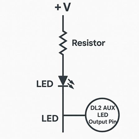
So you must provide:
- An external +V supply (typically 5ñ12V)
- A series resistor for each LED
- The LED itself
- Return the LED negative to the DL2 AUX pin
🔧 Correct Wiring Method
Hereís the safe, recommended wiring:
1. Choose your supply voltage
- 5V or 12V both work
- Use a resistor sized for your supply
2. Wire each LED like this
3. When the DL2 activates the LED
- The AUX pin pulls to ground
- Current flows through the resistor → LED → DL2 pin
- LED lights up
4. When the DL2 deactivates the LED
- The AUX pin is open circuit
- No current flows
- LED turns off
Typical Resistor Values
For a standard 20mA LED:
| Supply Voltage
| Resistor Value
|
| 5V
| 150ñ220 Ω
|
| 12V
| 470ñ680 Ω
|
If you want the LEDs dimmer (recommended for dashboards), use:
DL2 AUX Connector Pinout (relevant pins)
From the DL2 documentation:
| Pin
| Function
|
| 1
| Logging LED (switches to GND)
|
| 2
| Status LED (switches to GND)
|
| 3
| GPS Lock LED (switches to GND)
|
| 4
| Power LED (switches to GND)
|
| 5
| Ground
|
| 6
| 5V Reference (0.5A max)
|
| 7
| +V (input or output depending on config)
|
| 8
| 5V Reference (0.5A max)
|
| 9
| Log Button (switch to GND)
|
Important: Pins 6 and 8 are 5V reference outputs ó you can use them to power LEDs, but donít overload them. If you want multiple LEDs, itís safer to use an external 5ñ12V supply.
⚠️ Important Safety Notes
- Do NOT connect LEDs directly to the DL2 pins ó you will damage the output transistor.
- Do NOT exceed 20mA per LED output ó keep current low.
- Do NOT tie the LED cathode to chassis ground ó it must return to the DL2 AUX pin.
- If using 12V, always use a resistor ≥ 470 Ω.